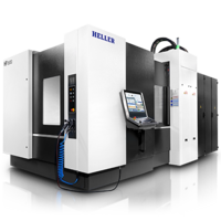
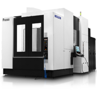
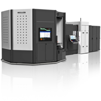
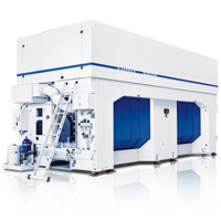
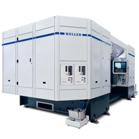
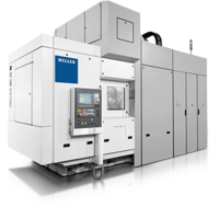
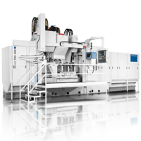
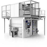
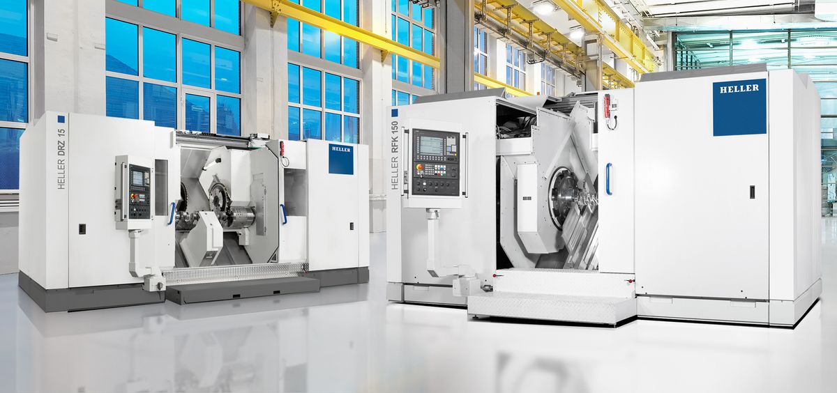
RFK crankshaft production systems
External milling of crankshafts
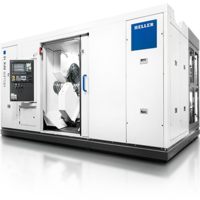
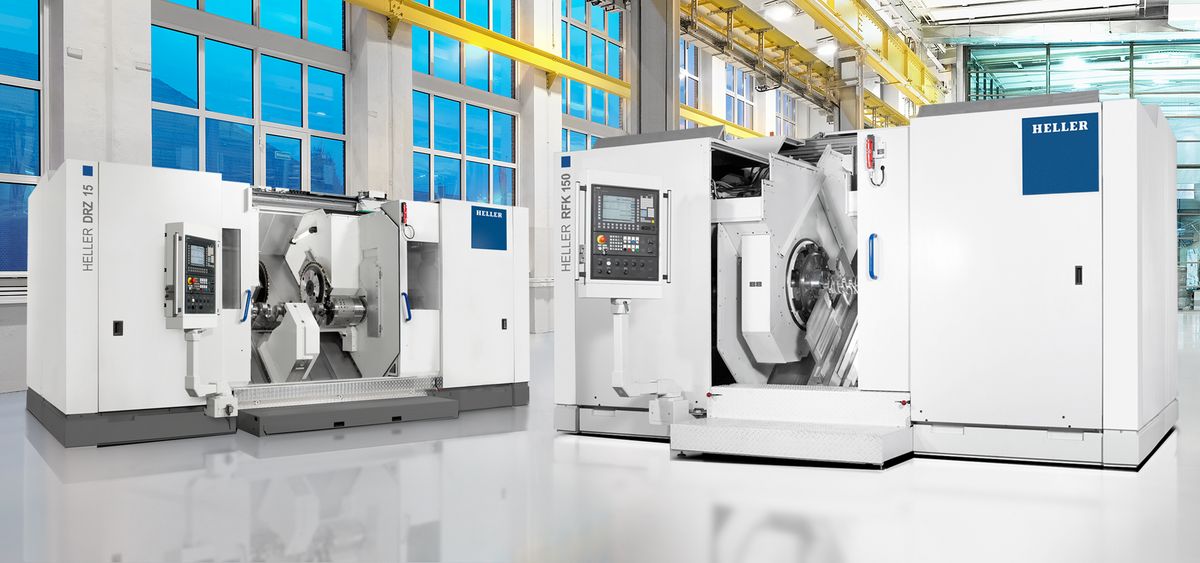
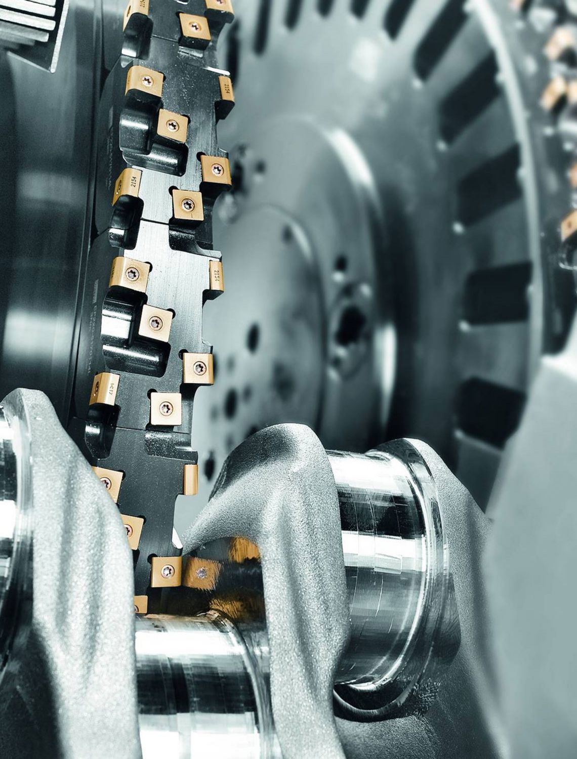
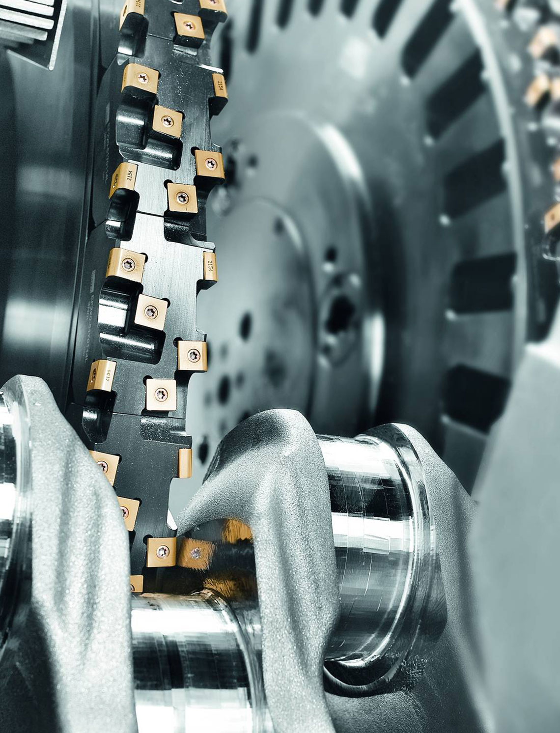
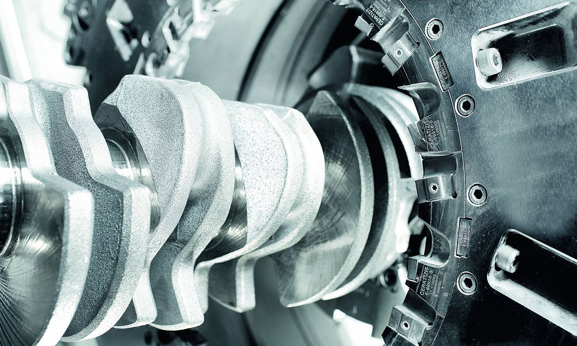
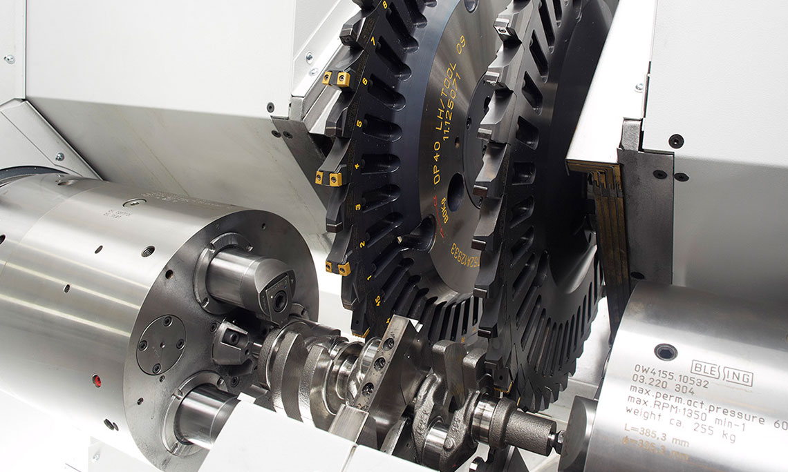
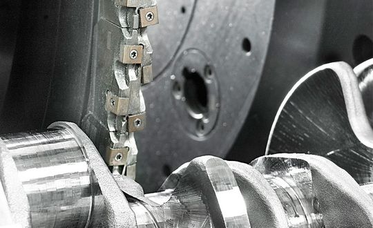
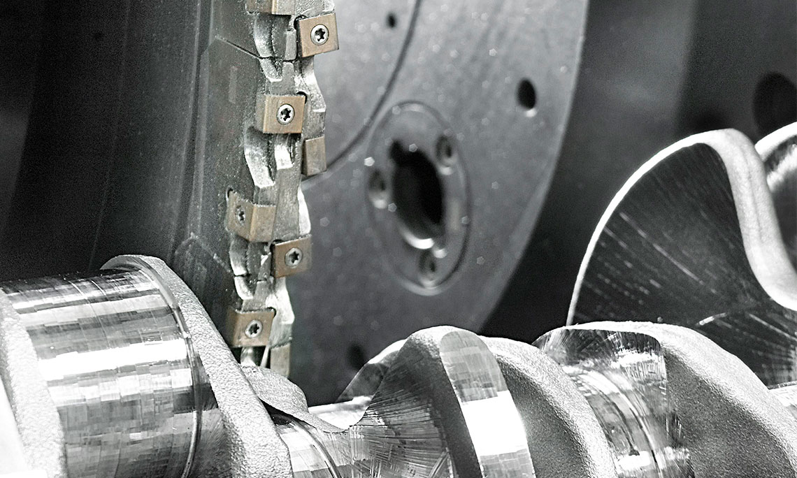
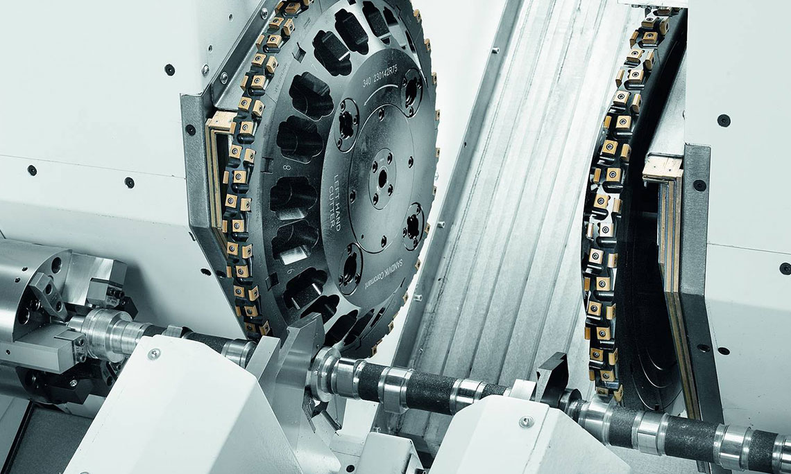
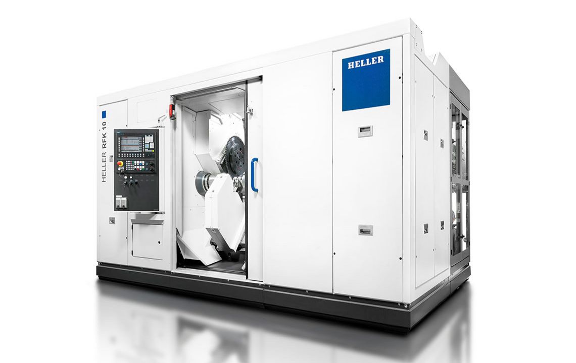
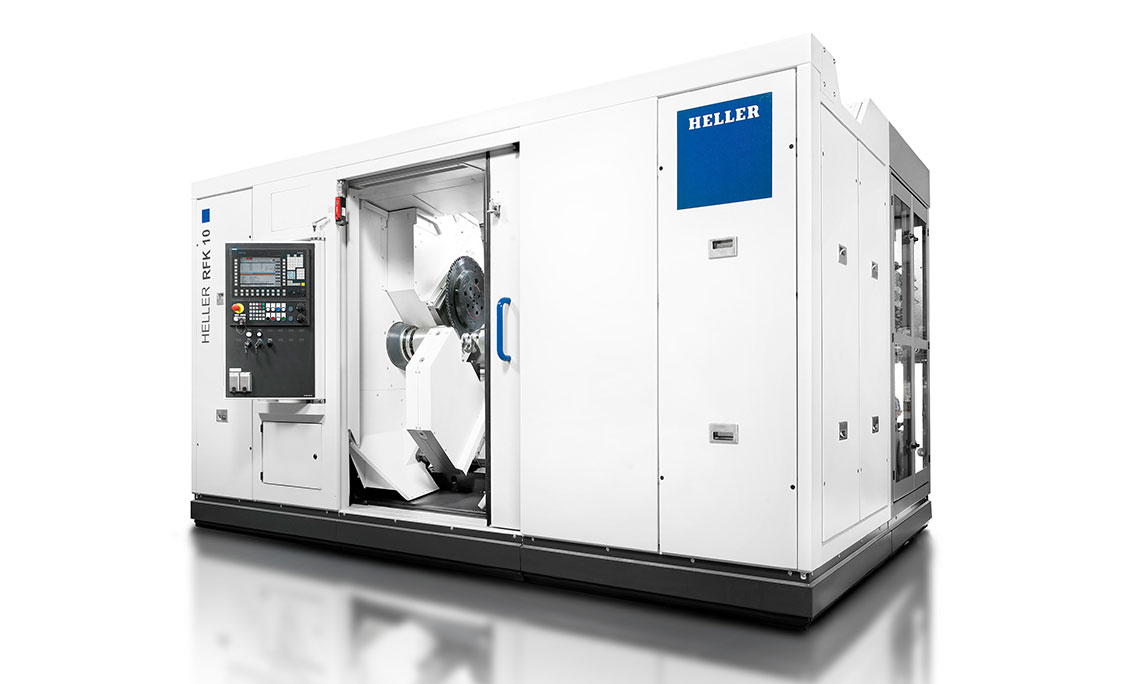
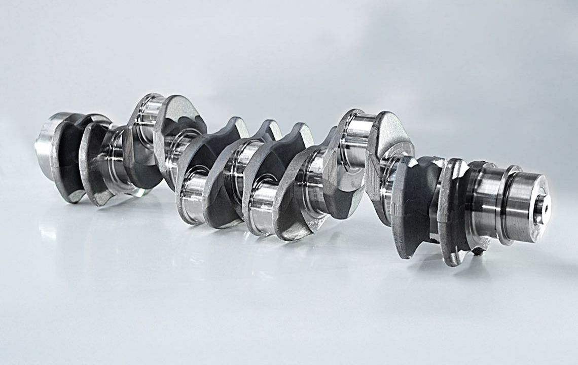
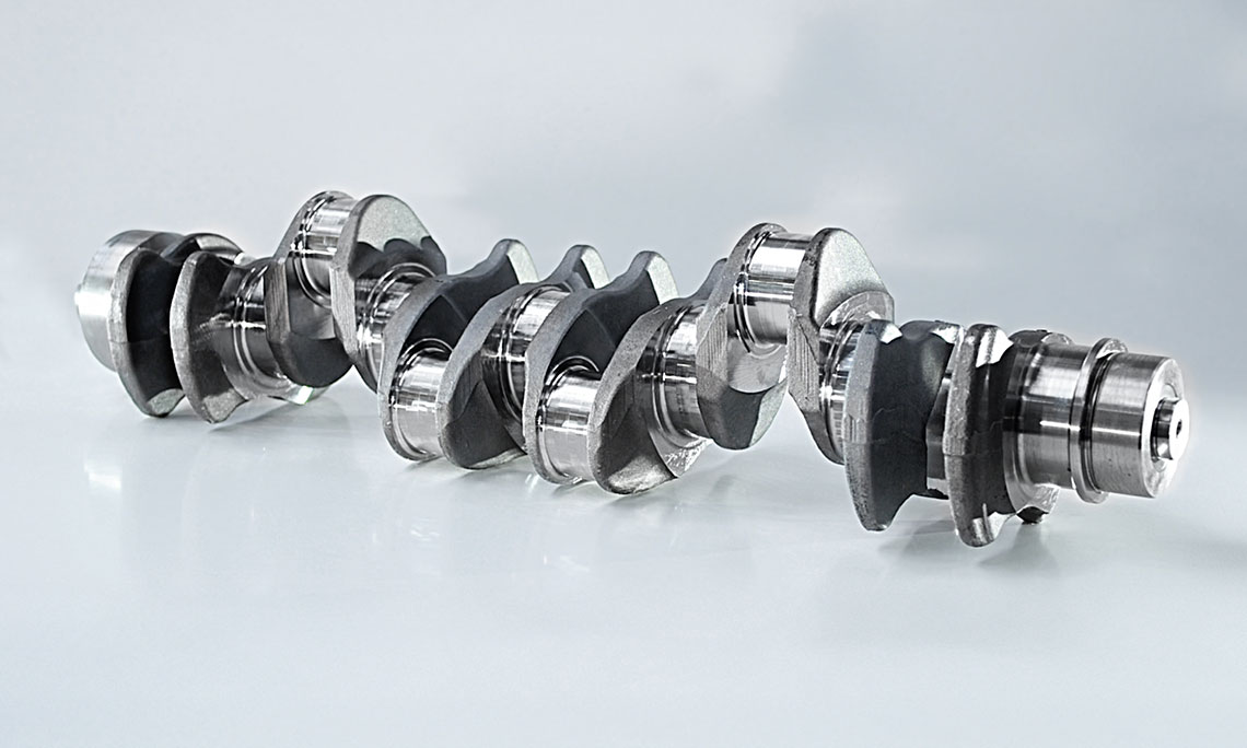
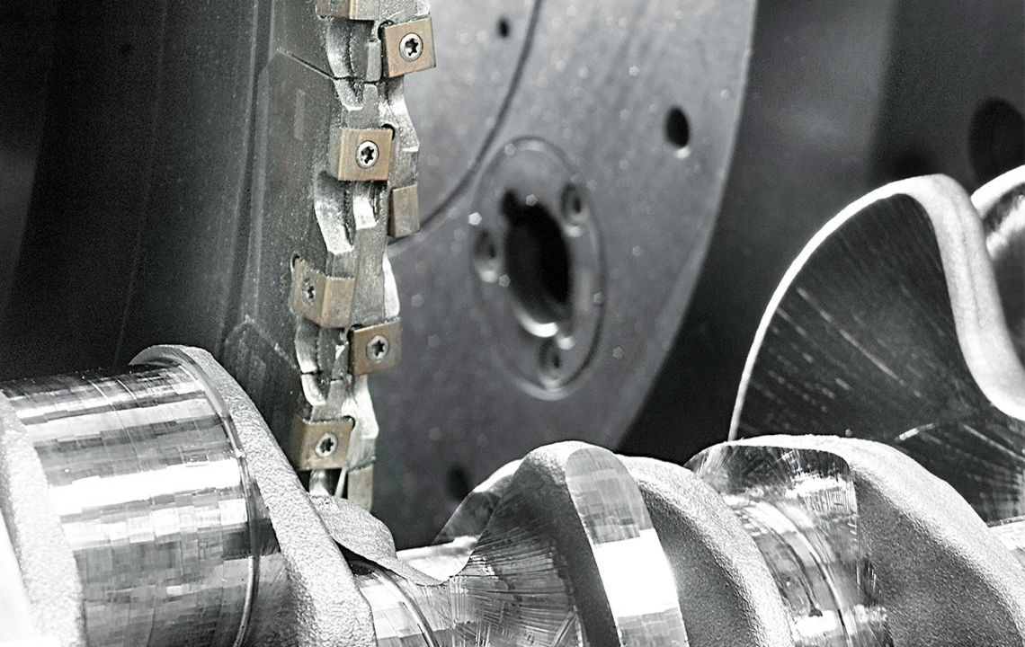
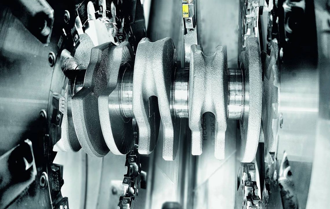
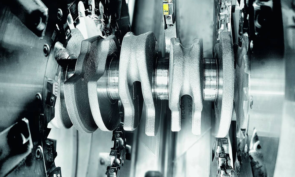
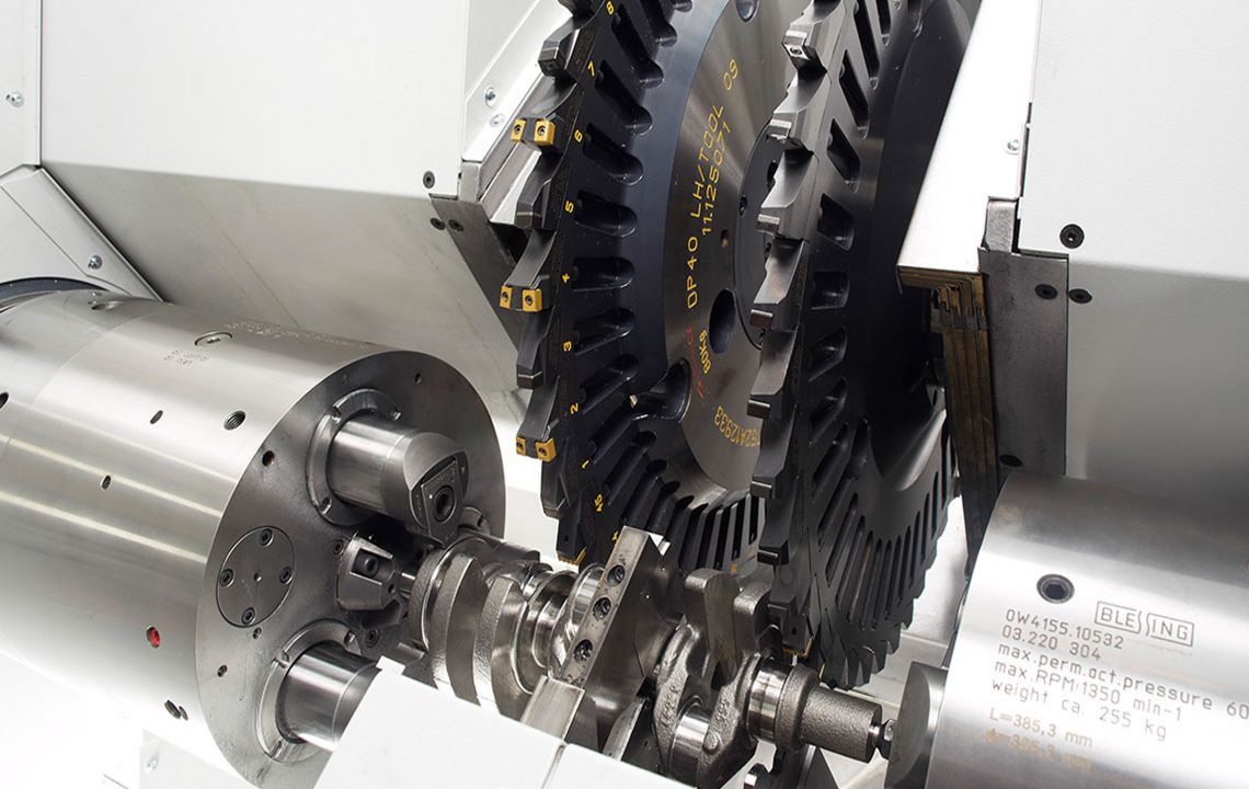
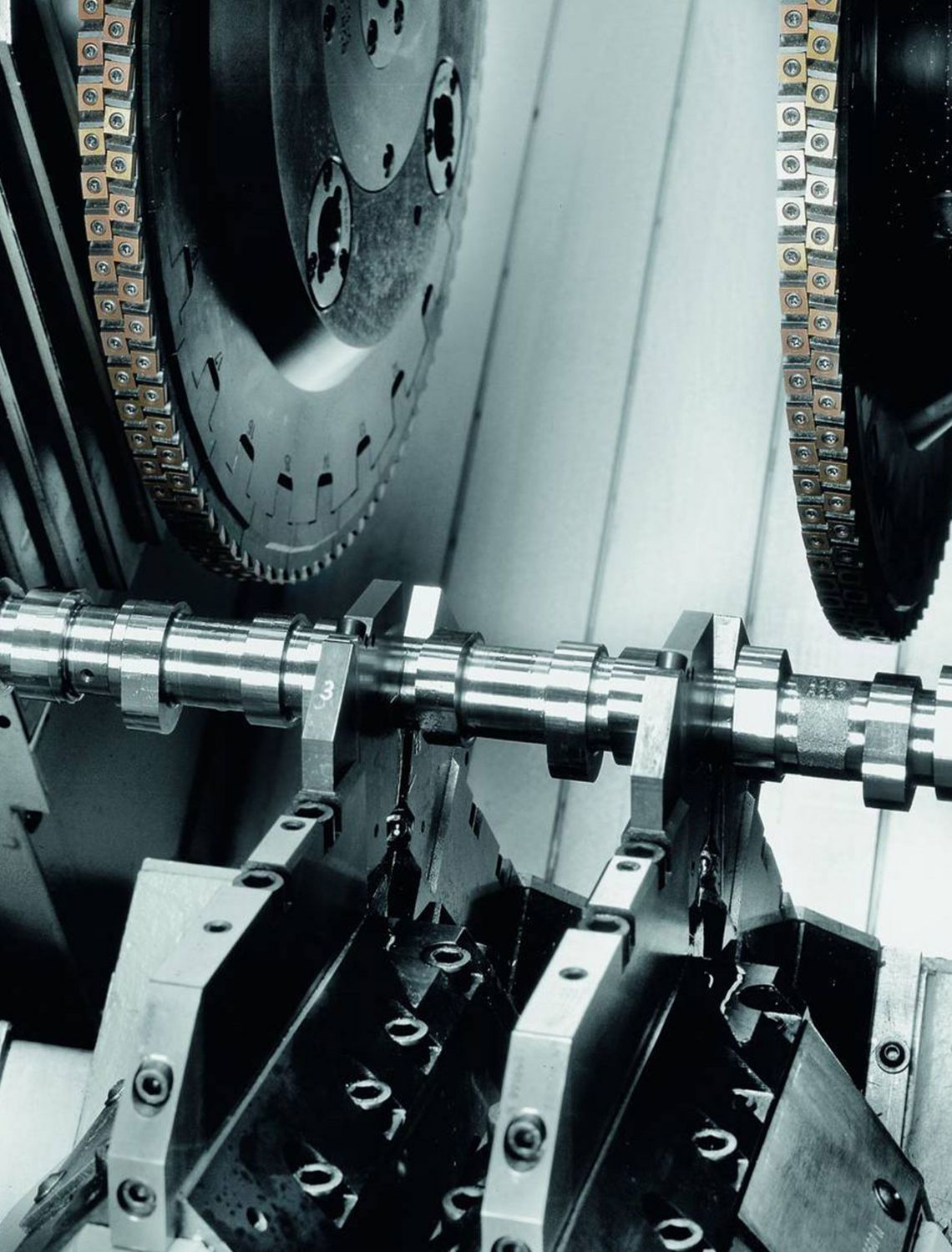
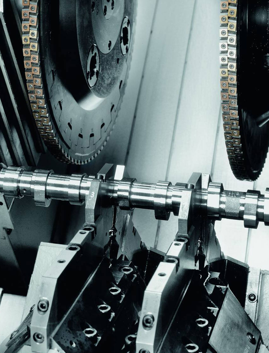
External milling is a flexible and productive method used primarily in the mass production of small to medium-sized crankshafts. The RFK crankshaft production systems from HELLER are for machining concentric and eccentric bearing points, cheek faces and cheek outer diameters as well as special contours in a highly productive manner – often in just one set-up.
- tool generates the cutting speed
- workpiece generates the feed rate
- use of external cutters
- tool profile is designed according to the profile to be milled
- for the machining of crankpins, 2 interpolating NC axes are used which are positioned eccentrically to the workpiece center and/or the concentric main bearings of crankshafts
- rotary feed is generated by the workpiece rotary axis, whilst the milling unit(s) is/are following as required using one/two linear axis/axes
- the plunge cut to the journal diameter is either carried out using the linear axis of the milling unit whilst the rotary axis is stationary or using a spiral motion with interpolation of the two axes. During the plunge cut, the cheek faces can be completely or partially machined
- in order to withstand cutting forces, workpieces are clamped and supported by two hydraulic clamping chucks with electrically synchronized rotation and by an additional steady rest which can be positioned using NC programming
- steady rest travels on a separate guideway below the milling slides to ensure unrestricted positioning within the travel path
- machining using one or two milling units is possible
- machining of bearing diameters and undercuts in a single operation is feasible
- simultaneous machining of main bearing and crankpin journal profiles is possible
- use of gang cutters is possible
- high precision of machined surfaces makes rough grinding obsolete
The following features can be machined (also in combination):
main bearings, crankpin journals, main bearings and crankpin journals in one set-up, cheek faces and cheek outer diameters, undercuts, cheek profiles
Technical data
| Product selection | RFK 10 | RFK 15 | RFK 30 | ||
| max. Workpiece length | mm | 500 | 600 | 1,250 | |
| max. Swing diameter | mm | 200 | 200 | 290 | |
| Tool diameter | mm | 700 | 700 | 800 | |
| max. Power | kW | 30 | 60 | 80 |
RFK crankshaft production systems
External milling of large crankshafts and eccentric shafts
- tool generates the cutting speed
- workpiece generates the feed rate
- use of external cutters
- tool profile is designed according to the profile to be milled
- for crankpin machining, 2 interpolating NC axes are used which are positioned eccentrically to the workpiece centre and/or the concentric main bearings of crankshafts
- rotary feed is generated by the rotary axis of the workpiece, with the milling unit(s) following as required using one/two linear axis/axes
- the plunge cut to the journal diameter is performed either by the linear axis of the milling unit alone, with the rotary axis stationary, or by a spiral motion with interpolation of the two axes – during plunge cutting, the cheek faces can be fully or partially machined
- to absorb cutting forces, workpieces are clamped and supported by two hydraulic clamping chucks with electrically synchronised rotation, plus one (RFK 30-2-2000) or two (RFK 30-2-4500) steady rests which can be positioned using NC programming
- steady rest travels on a separate guideway below the milling slides to ensure unrestricted positioning within the traverse path
- enables machining using one or two milling units
- bearing diameters and undercuts can be machined in a single operation
- enables simultaneous machining of mains and pin profiles
- enables use of gang cutters
- high precision of the machined surfaces eliminates the need for rough grinding
The following features can be machined (also in combination):
mains, pin bearings, main and pin bearings in a single set-up, cheek faces and cheek outer diameters, undercuts, cheek profiles
Technical data
| Product selection | RFK 30-2-2000 | RFK 30-2-4500 | ||
| max. Workpiece length | mm | 2,000 | 4,500 | |
| max. Swing diameter | mm | 350 | 485 | |
| Tool diameter | mm | 870 | 960 | |
| max. Power | kW | 60 | 60 |
RFK crankshaft production systems
Internal milling of crankshafts
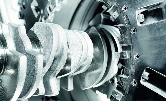
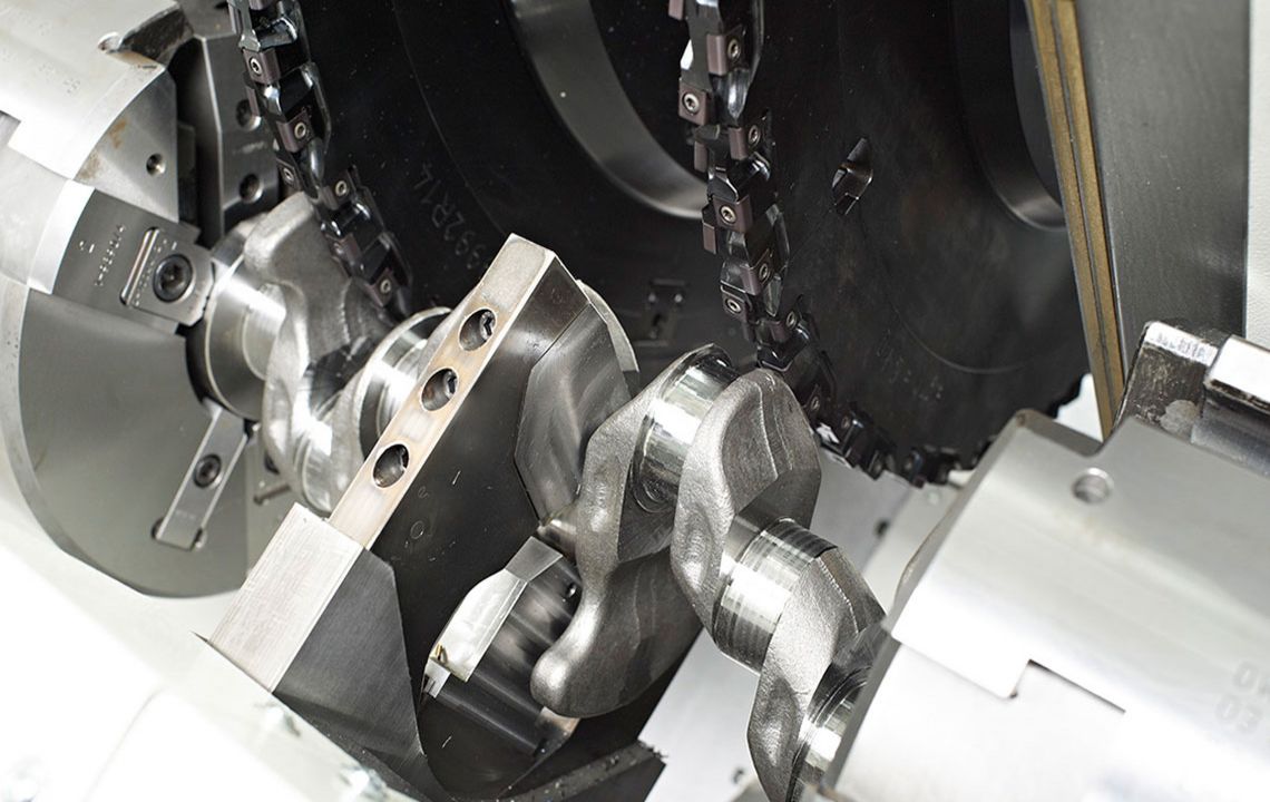
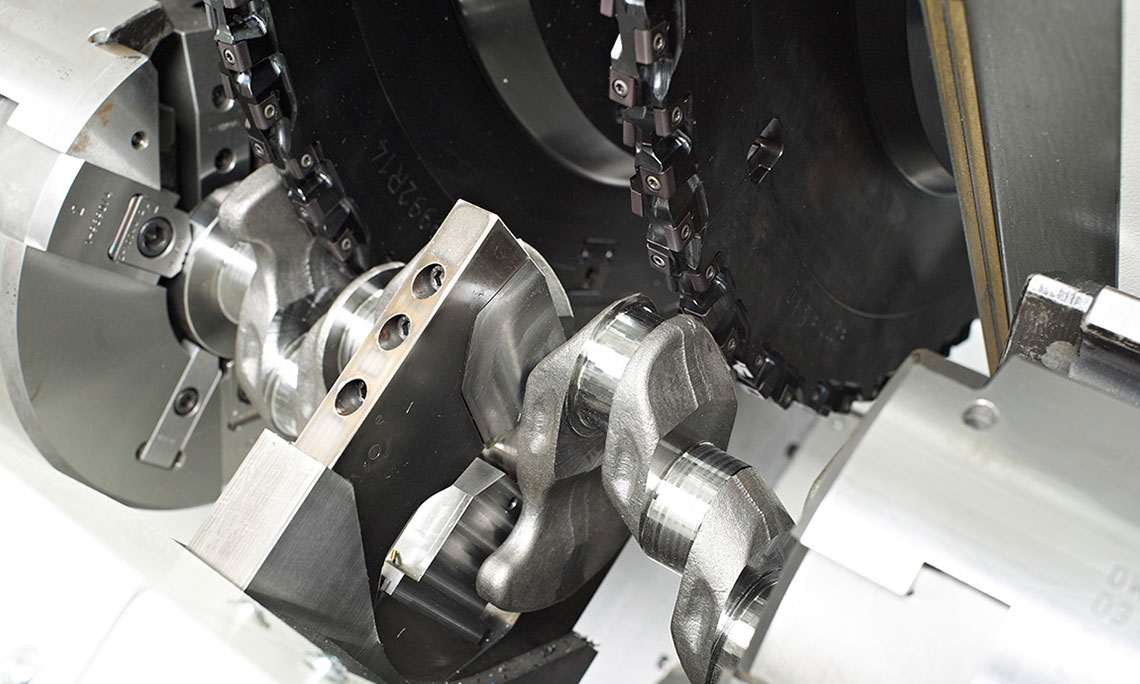
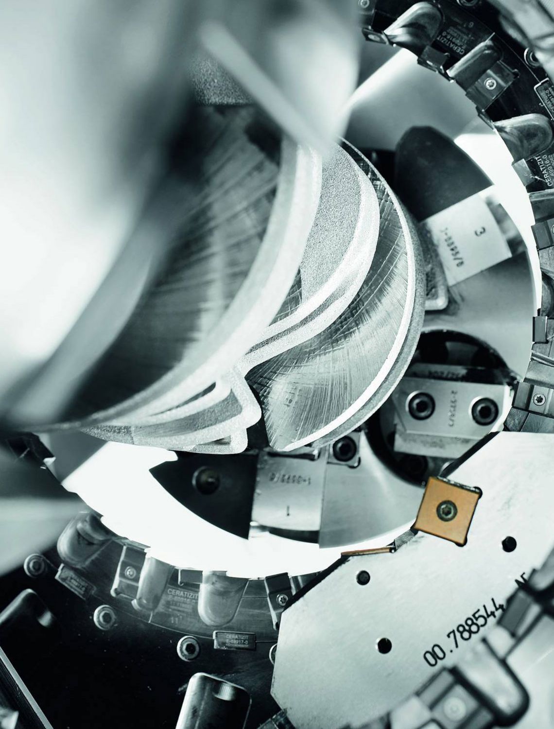
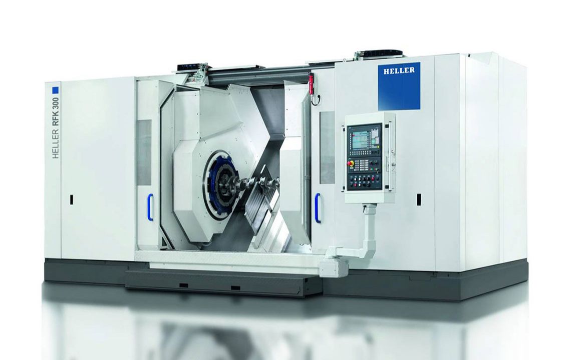
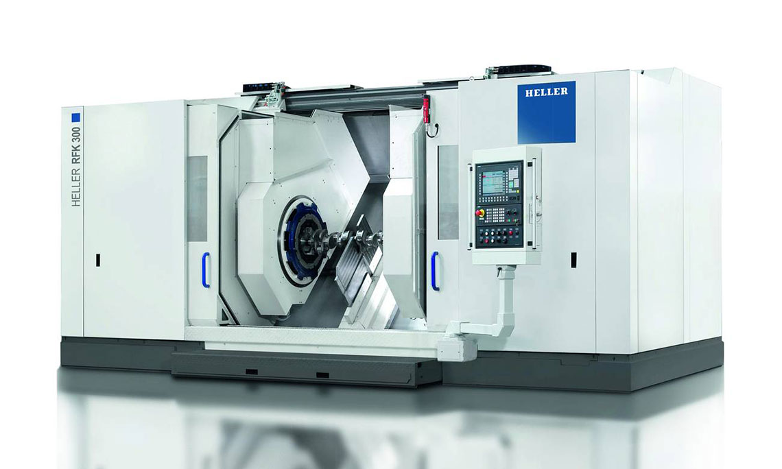
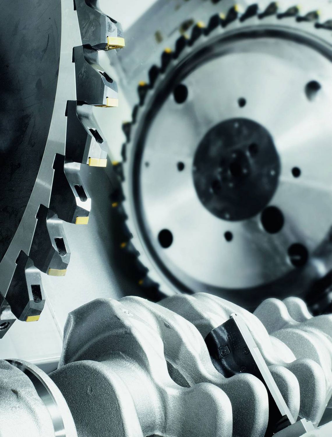
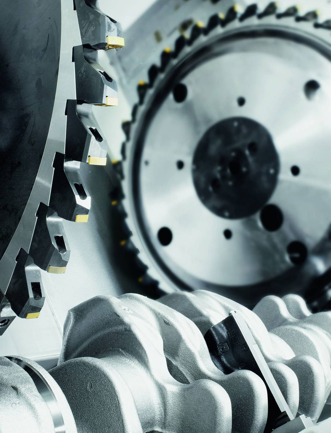
The internal milling of crankshafts is a productive machining method offering the best possible stability and machining accuracy with the highest stock removal rate. Thanks to the special machine component arrangement, the HELLER RFK crankshaft production system is able to accomplish even the most difficult machining tasks for very low part costs. Special tool concepts allow simple setting activities, as well as a fast tool change.
- tool generates the cutting speed
- workpiece generates the feed rate
- use of internal cutters
- the workpiece is surrounded by the tool, i.e. the inner tool diameter exceeds the maximum workpiece swing diameter and the clamping chuck diameter
- tool profile is designed according to the profile to be milled
- for the machining of crankpins, 2 interpolating NC axes are used which are positioned eccentrically to the workpiece center and/or the concentric main bearings of crankshafts
- rotary feed is generated by the workpiece rotary axis, whilst the milling unit(s) is/are following as required using one/two linear axis/axes
- the plunge cut to the journal diameter is either carried out using the linear axis of the milling unit whilst the rotary axis is stationary or using a spiral motion with interpolation of the two axes. During the plunge cut, the cheek faces can be completely or partially machined
- in order to withstand cutting forces, workpieces are clamped and supported by two hydraulic clamping chucks with electrically synchronized rotation and by an additional steady rest which can be positioned using NC programming
- steady rest travels on the guideway below the milling slides and is positioned between the two milling units on twin-spindle machines
- machining using one or two milling units is possible
- machining of bearing diameters and undercuts in a single operation is feasible
- simultaneous machining of main bearing and crankpin journal profiles is possible
- use of gang cutters is possible
- high precision of machined surfaces makes rough grinding obsolete
The following features can be machined (also in combination):
main bearings, crankpin journals, main bearings and crankpin journals in one set-up, cheek faces and cheek outer diameters, undercuts, cheek profiles
Technical data
| Product selection | RFK 100 | RFK 150 | RFK 300 | ||
| max. Workpiece length | mm | 500 | 600 | 1,250 | |
| max. Swing diameter | mm | 200 | 200 | 290 | |
| Tool diameter | mm | 230 | 275 | 310 | |
| max. Power | kW | 30 | 60 | 80 |
DRZ crankshaft production systems
Turn-chasing of crankshafts
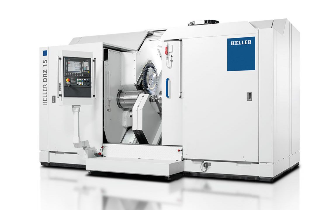
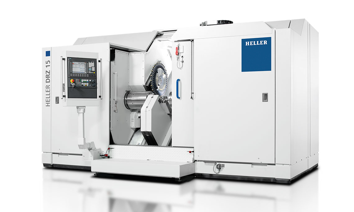
The turn-chasing of crankshafts is a highly productive machining method used primarily for mass production. HELLER DRZ crankshaft production systems permit maximum machining accuracies with high machining flexibility and long tool change intervals, coupled with extremely short chip-to-chip times.
- workpiece generates the cutting speed
- tool generates the feed rate
- plunge turning using standard inserts in combination with a chasing operation, specifically developed for this purpose and patented by HELLER, enables cost-effective and highly precise machining of any diameters and surfaces positioned concentric to the rotary axis
- extended tool operation times due to the use of duplicate cutting edges
- fast cutting edge change results in extremely short chip-to-chip-times
- automatic cutting edge measurement in two directions
- all concentric diameters (main bearings, undercuts, grooves, flange and stub end) can be machined in a single set-up
- robust machine design also allows heavy-duty cheek face cutting or cutting of the cheek outer diameter
- workpieces are clamped using two hydraulic, electronically synchronized clamping chucks; retractable clamping jaws are available as an option
- in order to withstand cutting forces, workpieces can be supported with an additional, steady rest positioned using NC programming
- steady rest travels on a separate guideway to ensure unrestricted positioning within the travel path
- machining using either one or two turn-chasing units is possible
- high precision of machined surfaces makes rough grinding obsolete
The following features can be machined (also in combination):
main bearings, undercuts and grooves, thrust bearings, flange diameters, stub-end diameters, concentric profiles, crankpin journals by means of eccentric clamping (special version), cheek faces and cheek outer diameters, chamfering (also eccentric and circumferential)
Technical data
| Product selection | DRZ 10 | DRZ 15 | DRZ 30 | ||
| max. Workpiece length | mm | 500 | 600 | 1,250 | |
| max. Swing diameter | mm | 200 | 200 | 290 | |
| Tool diameter | mm | 700 | 700 | 700 | |
| max. Power | kW | 30 | 48 | 48 |
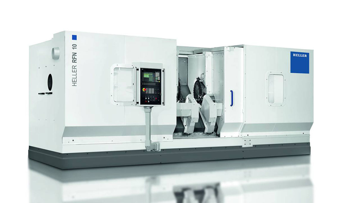
RFN camshaft production systems
External milling of camshafts
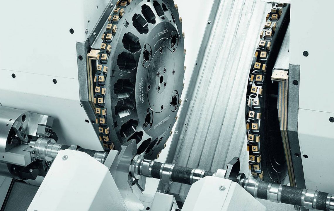
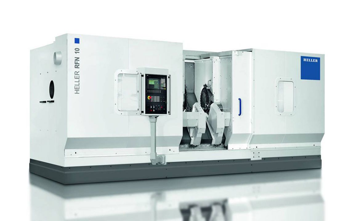
Camshaft machining – often directly from round material – requires the highest possible stock removal rate to be cost efficient. This places the toughest demands on the machining operation. HELLER RFN camshaft production systems put you on the safe side: You produce with high accuracy for optimal part costs.
- tool generates the cutting speed
- workpiece generates the feed rate
- use of external cutters
- cutter diameter can also be used for most hollow cam profiles.
- tool profile is designed according to the profile to be milled
- 2 interpolating NC axes are used for the machining of cam profiles
- rotary feed is generated by the workpiece rotary axis, whilst the milling unit(s) is/are following as required using one/two linear axis/axes
- the plunge cut to the cam profile is either carried out using the linear axis of the milling unit whilst the rotary axis is stationary or using a spiral motion with interpolation of the two axes
- in order to withstand cutting forces, workpieces are clamped and supported by two hydraulic clamping chucks with electrically synchronized rotation and by one or two additional steady rests which can be positioned using NC programming
- steady rests travel on a separate guideway below the milling slides to ensure unrestricted positioning within the travel path
- machining using one or two milling units is possible
- machining of cam profiles and chamfers in one operation is feasible
- use of gang cutters is possible
- radial alignment by means of bore or groove is possible
- high precision of machined contours makes rough grinding obsolete
The following features can be machined (also in combination):
cam profiles made of cast and forged camshafts, cam profiles made of bar stock, cam profiles with circumferential chamfers/profiles, cam interspaces (special application)
Technical data
| Product selection | RFN 10 | ||
| max. Workpiece length | mm | 1,250 | |
| max. Swing diameter | mm | 100 | |
| Tool diameter | mm | 450 | |
| max. Power | kW | 37 |
Downloads
At a glance, our Download Center offers an extensive range of information materials about our company, our products and services for you to download.
Contact
Contact
Sales & Services
Do you have questions about our products and services? Please get in touch with us, we are here for you! Benefit from our global HELLER network with knowledgeable sales and service contacts located in your region.
Find your nearest personal contact.
No results could be found.
You might also be interested in
HELLER Newsletter
Register now!
The HELLER Newsletter provides you with information about all current topics concerning our company, our products and services as well as upcoming trade shows and events. Register now to make sure you never miss any news from the HELLER Group!


